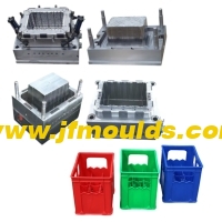
กลไกการดึงแกนด้านข้างของ
กลไกการดึงแกนด้านข้างของ "คอลัมน์นำแบบเอียงตัวเลื่อน"
I. การจำแนกประเภทของการพิมพ์ด้านข้างและกลไกการดึงแกนกลาง
ตามลักษณะโครงสร้าง กลไกการดึงแกนด้านข้างแบ่งออกเป็นหกประเภทหลักดังต่อไปนี้
กลไกการดึงแกนด้านข้างของ "คอลัมน์นำแบบเอียงตัวเลื่อน"
2. กลไกการดึงแกนด้านข้างของ "slider bent pin"
3. กลไกการดึงแกนด้านข้างของ "บล็อกรูปตัว T ของตัวเลื่อน"
4. กลไกการดึงแกนด้านข้างของ "กระบอกไฮดรอลิกแบบเลื่อน"
5. กลไกการดึงแกนด้านบนด้านข้างเอียง
6. กลไกการดึงแกนด้านข้างของแถบเลื่อนแบบเอียง
สอง: ด้านข้างของ "คอลัมน์แนะนำแบบเลื่อนเอียง"
การออกแบบเสานำแบบเอียงและบล็อกแรงดันของคอลัมน์นำแบบเอียง

ผู้ผลิตแม่พิมพ์ฉีดฝาขวดในประเทศจีน (jfmoulds.com)
มุมเอียง
ภายใต้สถานการณ์ปกติ สำหรับ a=15° ถึง 25° มุมที่ใช้กันทั่วไปคือ 18° และ 20&องศา; ภายในช่วงนี้ ยิ่ง a มีค่าน้อยเท่าไรก็ยิ่งดีเท่านั้น เพราะยิ่ง a มีค่าน้อย แรงบิดที่คอลัมน์นำทางแบบเอียงก็จะยิ่งน้อยลง และแรงเสียดทานที่ไหล่ของตัวเลื่อนก็จะน้อยลงเท่านั้น
2. เมื่อระยะการดึงแกนมีขนาดเล็กและตัวเลื่อนค่อนข้างสูง มุมเอียง สามารถใช้ค่าที่น้อยกว่าได้ แต่ค่าต่ำสุดต้องไม่น้อยกว่า 10° เมื่อระยะการดึงแกนมีขนาดใหญ่ มิติความสูงของตัวเลื่อนมีขนาดเล็ก และแรงจับยึดของชิ้นส่วนพลาสติกในการดึงแกนด้านข้างก็มีน้อยเช่นกัน นั่นคือมุมเอียง สามารถใช้ค่าที่มากขึ้นได้ แต่ค่าสูงสุดต้องไม่เกิน 30°
ขนาดของ a ขึ้นอยู่กับระยะห่างของการดึงแกนด้านข้างและความสูงของตัวเลื่อน และไม่ขึ้นอยู่กับระยะดีดออกของชิ้นส่วนพลาสติก โดยทั่วไปแล้ว ภายใต้สถานที่ตั้งของการปฏิบัติตามข้อกำหนดระยะทางในการดึงแกนด้านข้าง ส่วนหัวของคอลัมน์นำที่มีความลาดเอียงควรอยู่ใกล้กับพื้นผิวด้านล่างของแถบเลื่อนมากที่สุด หากแกนนำแบบเอียงสั้นเกินไปและส่วนหัวอยู่ห่างจากพื้นผิวด้านล่างของตัวเลื่อน ตัวเลื่อนจะได้รับแรงบิดที่ค่อนข้างสูงในระหว่างการดึงแกน แรงบิดนี้จะเพิ่มแรงเสียดทานระหว่างไหล่ของตัวเลื่อนและบล็อกแรงดันหรือช่องตัว T และอย่างน้อยที่สุด จะเร่งการสึกหรอของพื้นผิวแรงเสียดทาน ในกรณีที่รุนแรง อาจทำให้แถบเลื่อน "ติด" และป้องกันไม่ให้แกนถูกดึงออกมา ดังนั้นในระยะเริ่มต้นของการดึงแกน ความยาวสัมผัสระหว่างคอลัมน์นำเอียงและรูตัวเลื่อนไม่ควรน้อยกว่าสองในสามของความยาวของรูเอียงของตัวเลื่อน ในทางตรงกันข้าม หากหมุดนำแบบเอียงยาวเกินไปและจำเป็นต้องขยายออกไปเกินพื้นผิวด้านล่างของตัวเลื่อนอย่างมาก ในขณะที่กระบวนการดึงแกนดำเนินไป เนื่องจากความยาวที่เพิ่มขึ้นของแขนคันโยก แรงบิดที่เกิดจากหมุดนำแบบเอียงจะเพิ่มมากขึ้นเรื่อยๆ และในที่สุดจะนำไปสู่การโค้งงอและการเสียรูปของหมุดนำแบบเอียง หากขนาดของความสูงของตัวเลื่อนมีขนาดเล็กเนื่องจากมีระยะดึงแกนที่มาก หัวของคอลัมน์นำที่มีความลาดเอียงจะต้องยื่นออกไปเลยพื้นผิวด้านล่างของตัวเลื่อน ขอแนะนำว่าความยาวที่ขยายต้องน้อยกว่าหนึ่งในสามของความยาวของรูเอียงของตัวเลื่อน

(2) Chamfer e ที่ส่วนหัวของคอลัมน์นำแบบเอียง
e ควรมากกว่าหรือเท่ากับมุมเอียง a ของคอลัมน์นำเอียงเพื่อให้แน่ใจว่ามีปัจจัยด้านความปลอดภัยเพียงพอเมื่อสอดคอลัมน์นำเอียงเข้าไปในรูเอียงของตัวเลื่อน เมื่ออยู่ที่ ≥18° หัวของคอลัมน์นำเอียงควรหลีกเลี่ยงการเป็นครึ่งวงกลมให้มากที่สุด
(3) ความยาว L ของคอลัมน์บอกแนวเอียงสามารถคำนวณได้จากสูตรพื้นฐานของฟังก์ชันตรีโกณมิติ :L=L1 L2=S/sina H/cosa
H ความหนาของแผ่นคงที่ ระยะดึงแกน S; มุมเอียงของคอลัมน์นำเอียง
สาม: การออกแบบบล็อกแรงดันสไลเดอร์และสไลเดอร์
(1) การนำทางของตัวเลื่อน
ควรสังเกตประเด็นต่อไปนี้เมื่อออกแบบตัวเลื่อน
การทำงานของตัวเลื่อนควรราบรื่นและปลอดภัย เพื่อให้แน่ใจว่าการดึงแกนด้านข้างจะราบรื่นโดยไม่มีการติดขัด ช่องว่างในร่องสไลด์ควรสม่ำเสมอ ไม่มีการหลวมหรือแน่นเกินไป ค่าเผื่อความพอดีระหว่างตัวเลื่อนและเบาะนั่งแบบสไลด์คือ H7/f7
2. Oil grooves should be provided on the sliding surface of the large slider, and there must be cooling water channels
When the sliding stroke of the slider is too long, the guide groove must be extended on the mold base. Generally, the length of the sliding part should be about 1.5 times the height. When extracting the core, the length of the slider beyond the mold frame should not exceed one quarter of the slider's length; otherwise, the guide slide groove should be added
Long.
4. The wedge block of the slider must be inserted into the lower die for locking, with an insertion depth of 10 to 20mm and a locking Angle of 5° to 10°.
The design considerations for the slider pressure plate are as follows.
The material of the pressure plate is 718.
2. Surface ammonia infiltration treatment.
3-edge chamfer C1.
4. Processing oil grooves on sliding mating surfaces.
5. Selection of the pressure plate
a. Standard specifications should be given priority for the pressure plate, followed by the "7" shape
B. The upper end face of the pressure plate should be as flush as possible with the template surface to ensure the mold's aesthetic appearance
c. The pressure plate should be avoided from being pressed simultaneously on the inner mold inserts and the template as much as possible.
d. To prevent deformation, the length of the pressure plate should be controlled under 200mm as much as possible.
(2) Positioning of the slider during mold closing
1. General requirements for positioning
A. The positioning surface should be selected as a plane.
B. The positioning surface should be selected on relatively fixed parts, such as moving and fixed mold inserts, mold bases, etc., and must not be selected on sliders and movable inserts
c. When the slider is used for relative positioning, the slope of the positioning surface should be more than 5° on one side
d. The positioning requirements for the fixed mold slider are high because wire clamping can affect the appearance of the plastic part, so more attention should be paid. The positioning method is basically the same as that of the moving mold slider.
2. For individual sliders, the sliders shown in (a), (B ), and (c) have good positioning effects.
3. For the Haff slider (also known as the split slider). The following points should be noted when designing.
A. Each slider must have a reliable positioning. Generally, it is positioned by inserts. In cases where inserts cannot be used for positioning, separate positioning blocks should be adopted for positioning.
B. It is strictly prohibited to directly position the Haff slider with circular cores, push rods, push tubes or small inserts (these parts are prone to deformation under force).
c. There must also be a process positioning block between the two sliders to ensure that the plastic part does not grade at the wire clamping point.
d. It is essential to ensure that the inner mold inserts have sufficient positioning strength in the sliding direction.
e. The slider is not precisely positioned by directly using the arc surface of the moving mold insert. Therefore, a positioning block must be added to the insert (the positioning block is inserted into the mold base).
ข้อมูลที่เกี่ยวข้อง
ระบายเหล็กระบายอากาศของแม่พิมพ์ออก
2025-10-17
ท่อไอเสียเหล็กระบายอากาศของแม่พิมพ์ เหล็กที่ซึมเข้าไปได้เป็นโลหะผสมซินเทอร์...

ข้อมูลเชิงลึกแบบพาโนรามาในอุตสาหกรรมแม่พิมพ์ฉีด: การปลอมข้างหน้าในคลื่นของการเปลี่ยนแปลง
2025-07-04
ข้อมูลเชิงลึกแบบพาโนรามาในอุตสาหกรรมแม่พิมพ์ฉีด: การปลอมข้างหน้าในคลื่นของ...
การแก้ปัญหาสายอากาศและการเติมที่ไม่สมบูรณ์ (ขาดกาว) ในแม่พิมพ์
2025-08-09
การแก้ปัญหาสายอากาศและไส้ที่ไม่สมบูรณ์ (ขาดกาว) ในแม่พิมพ์อากาศ ...
วิธีแก้ปัญหาการเยื้องยางแข็งตำแหน่งแถวที่ลดระดับและขนาดผลิตภัณฑ์ที่ไม่สอดคล้องกันในแม่พิมพ์
2025-08-29
วิธีแก้ปัญหาการเยื้องยางแข็งตำแหน่งแถวที่จะลดระดับและ ...
แม่พิมพ์ฉีด: การผลิตเฉพาะเสริมประสิทธิภาพการผลิตคุณภาพใหม่ในอุตสาหกรรม
2025-07-14
แม่พิมพ์ฉีด: การผลิตพิเศษเพิ่มขีดความสามารถในการผลิตคุณภาพใหม่...
การปรับอากาศที่ติดอยู่ของแม่พิมพ์เป็นเรื่องยากและการเสียรูปและวิธีการดึงตำแหน่งแถวด้านล่างดึงวิธีการรักษาเชื้อราของเปลือกใบหน้า
2025-08-12
การปรับอากาศที่ติดอยู่ของแม่พิมพ์นั้นยากและการเสียรูปและ ...