การทำเครื่องหมายมิติของการวาดการออกแบบแม่พิมพ์
การทำเครื่องหมายมิติของการวาดการออกแบบแม่พิมพ์
I. ข้อกำหนดทั่วไปสำหรับการทำเครื่องหมายมิติในภาพวาดการออกแบบแม่พิมพ์
1. หน่วยที่ใช้สำหรับการทำเครื่องหมายมิติ: หน่วยมิติในการวาดรูปแม่พิมพ์รวมถึงตัวชี้วัดและระบบของจักรวรรดิ ในหมู่พวกเขาประเทศต่าง ๆ เช่นสหราชอาณาจักรสหรัฐอเมริกาแคนาดาอินเดียและออสเตรเลียใช้ระบบจักรวรรดิในขณะที่จีนใช้ระบบการวัด อย่างไรก็ตามหากลูกค้ามาจากประเทศใด ๆ ข้างต้นขอแนะนำให้ใช้ระบบจักรวรรดิ นอกจากนี้ชิ้นส่วนมาตรฐานจำนวนมากในแม่พิมพ์ (เช่นสกรูแท่งดัน ฯลฯ ) อยู่ในหน่วยจักรวรรดิ ดังนั้นแม้ว่ามิติอื่น ๆ จะอยู่ในระบบเมตริกในระหว่างการออกแบบแม่พิมพ์ขนาดของชิ้นส่วนมาตรฐานเหล่านี้ยังคงมีการทำเครื่องหมายในหน่วยอิมพีเรียล
2. ความแม่นยำที่นำมาใช้เมื่อทำเครื่องหมายมิติ
ขนาดเชิงเส้น: ระบบเมตริกใช้ทศนิยมสองตำแหน่ง x.xxmm และระบบอิมพีเรียลใช้ทศนิยมสี่ตำแหน่ง x.xxxxin
มุม: ใช้ทศนิยมหนึ่งตำแหน่ง: x.x °
3. การอ้างอิงมิติในการวาดรูปแม่พิมพ์
. การอ้างอิงผลิตภัณฑ์ (ส่วนพลาสติก): การอ้างอิงตามภาพวาดผลิตภัณฑ์ของลูกค้า มิติทั้งหมดของโพรงและแกนจะต้องขึ้นอยู่กับการอ้างอิงชิ้นส่วนพลาสติกเป็นการอ้างอิงการออกแบบ
ขนาดของแกนและโพรงในการวาดการออกแบบแม่พิมพ์ควรสอดคล้องกับหนึ่งต่อหนึ่งกับสิ่งที่อยู่ในการวาดภาพผลิตภัณฑ์
ข. การอ้างอิงการประกอบแม่พิมพ์: โดยทั่วไปศูนย์กลางของฐานแม่พิมพ์จะถูกนำมาเป็นอ้างอิงการประกอบ มิติทั้งหมดที่เกี่ยวข้องกับการประกอบฐานแม่พิมพ์เช่นรูสกรูและรูน้ำเย็นควรขึ้นอยู่กับการอ้างอิงการประกอบเป็นการอ้างอิงการออกแบบ
ค. การอ้างอิงกระบวนการ: การอ้างอิงที่กำหนดขึ้นอยู่กับข้อกำหนดการประมวลผลและการวัดของชิ้นส่วนแม่พิมพ์เช่น counterbore ของรูแทรกควรขึ้นอยู่กับพื้นผิวด้านล่าง
วิธีการเลือกของการอ้างอิงมิติสำหรับการวาดแม่พิมพ์มีดังนี้
. ในมุมมองส่วนพื้นผิวการแยกจะถูกนำมาใช้เป็นข้อมูลอ้างอิงและมีการเพิ่มสัญลักษณ์อ้างอิงพร้อมกัน บางครั้งวิศวกรผลิตภัณฑ์อาจต้องการการอ้างอิงตามการวาดส่วนพลาสติก ในกรณีเช่นนี้การอ้างอิงชิ้นส่วนพลาสติกเกิดขึ้นพร้อมกับการวาดรูปแม่พิมพ์
ข. ในแผนชั้นสถานการณ์ค่อนข้างซับซ้อนและควรได้รับการปฏิบัติแตกต่างกัน
หากชิ้นส่วนพลาสติกมีความสมมาตรให้ใช้สองเส้นกลางเป็นข้อมูลอ้างอิงและเพิ่มสัญลักษณ์อ้างอิงในเวลาเดียวกัน
หากมีเพียงแกนเดียวเท่านั้นที่สมมาตรในขณะที่อีกแกนหนึ่งนั้นไม่สมมาตรและหากมีตำแหน่งคอลัมน์ศูนย์กลางของคอลัมน์ควรใช้เป็นข้อมูลอ้างอิง หากไม่มีตำแหน่งคอลัมน์ให้ใช้เส้นตรงหรือขอบตรงเป็นข้อมูลอ้างอิง
หากแกนทั้งสองไม่สมมาตรให้เลือกตำแหน่งคอลัมน์หรือด้านตรงเป็นข้อมูลอ้างอิง
การเลือกที่ถูกต้องของการอ้างอิงมิติเป็นเงื่อนไขที่สำคัญสำหรับการรับรองข้อกำหนดการออกแบบของชิ้นส่วนและอำนวยความสะดวกในการประมวลผลและการวัด

ผู้ผลิตแม่พิมพ์พัดลมในประเทศจีน (jfmoulds.com)
4. การวัดขนาดของโครงสร้างเดียวกันควรมีความสม่ำเสมอในความพยายามที่แตกต่างกัน ตัวอย่างเช่นทำเครื่องหมายอย่างสม่ำเสมอตามขนาดปลายขนาดใหญ่ หากจำเป็นควรทำเครื่องหมายมุม demolding เช่น 50 ± 3 ° สำหรับขนาดของซี่โครงเสริม (ซี่โครง) และรูเฉพาะขนาดกลางความกว้างความลึกและเส้นผ่านศูนย์กลางจะต้องทำเครื่องหมาย ควรทำเครื่องหมายมุม demolding แยกกัน
5. ตำแหน่งและขนาดของรูก้านดันจะต้องทำเครื่องหมายบนการวาดรูปแม่พิมพ์ภายในเท่านั้น พวกเขาไม่จำเป็นต้องทำเครื่องหมายบนแผ่นยึดก้านกดหรือการวาดรูปแบบแม่แบบ แต่ควรระบุเส้นผ่านศูนย์กลางของรูก้านดัน
6. สำหรับชิ้นส่วนกลึงของ CNC ไม่จำเป็นต้องทำเครื่องหมายมิติทั้งหมด เฉพาะข้อมูลอ้างอิงที่สำคัญและข้อมูลการตรวจสอบเท่านั้นที่จะต้องทำเครื่องหมาย
7. ขนาดหลักที่ทำเครื่องหมายไว้บนเม็ดมีดที่เคลื่อนที่และคงที่คือ: การตัดลวด; สกรู, รูน้ำเย็น, รูก้านดัน; ความแตกต่างความสูงของพื้นผิวแยก มิติการจับคู่ของรูปร่าง ฯลฯ เพื่อความชัดเจนสามารถทำเครื่องหมายด้านบนในภาพวาดหนึ่งภาพขึ้นไป
8. สำหรับขนาดที่ตัดลวดควรทำเครื่องหมายมิติหลักเท่านั้น สำหรับรูปทรงที่ซับซ้อนชิ้นส่วนลวดตัดสามารถคัดลอกและวาดแยกต่างหากและระบุไว้ในภาพวาดต้นฉบับ
9. ฐานแบบหล่อที่ไม่ได้มาตรฐานจะต้องทำเครื่องหมายด้วยตำแหน่งและขนาดของหลุมสกรูชนิดเทมเพลต, แท่งรีเซ็ต, พินคู่มือ, ฯลฯ เช่นเดียวกับขนาดการตรวจจับ NC ของเฟรมการเคลื่อนที่และการคงที่ อย่างไรก็ตามไม่จำเป็นต้องทำเครื่องหมายฐานแบบหล่อมาตรฐาน (และพินไกด์, แท่งรีเซ็ตและหมุดคู่มือก้านแบบกดไม่ได้รับคำสั่งในชิ้นส่วนมาตรฐานอีกต่อไป)
เมื่อทำเครื่องหมายตำแหน่งการประมวลผลของอิเล็กโทรดซี่โครงเสริมแรงคุณจำเป็นต้องทำเครื่องหมายตำแหน่งกึ่งกลางของอิเล็กโทรดเท่านั้น
Car Mould_Taizhou jiefeng Mold Co.,Ltd. (jfmoulds.com)
Ii. Requirements for Dimension Marking of Assembly Drawings
1. The ranking map adopts the coordinate annotation method, with the center of the mold as the coordinate origin. The sectional view adopts linear dimensioning.
2. The assembly drawing mainly marks the following dimensions.
a. Dimensions of the connection parts of the injection molding machine;
b. The dimensions of all parts that are not separately drawn in the part drawing (mainly the processing part of the mold frame), but the positions of the standard holes on the mold frame may not be marked
c. Position and size of each cavity, and try to take the nearest whole number;
d. The position of the gate and the gate sleeve screws;
e. The size of the template and the size and position of the inner mold inserts;
f. The position and size of the lateral core-pulling mechanism and its accessories;
8. The position and size of the positioning block;
h. Location, specification and number of cooling water holes;
The diameter and position of holes i.K.O;
J. The length and size of the guide pins and guide sleeves of the push rod plate;
k. Position and diameter of the support columns (S.P);
1. The diameter and length of the reset spring, the depth and diameter of the spring hole, and the spring specification should be marked;
m. The diameter and thickness of the limit nail;
n. The position and length of the spacing parting mechanism in the three-plate mold and the two-plate half-mold.
Three: Requirements for dimension marking of parts
1. Correct: Dimensional marking should comply with the basic provisions of the national standard "Mechanical Drawing"
2. Completeness: Dimensional annotations must ensure that all production activities in the factory can proceed smoothly and facilitate reference and search based on the drawings.
3. Clarity: The size configuration should be uniform and standardized
4. Reasonable: The dimensional marking should comply with the design and process requirements to ensure the performance of the mold.
5. For parts with a slope, the "large" and "small" should be noted beside the dimension marking to indicate the dimensions of the large and small ends.
6. Basic Requirements: The maximum external dimensions must be directly marked on the drawing. If a closed dimension chain is generated, parentheses can be added to the maximum external dimension.
7. Dimensions should be marked outside the view as much as possible to avoid the intersection of dimension lines, dimension numbers and the contour lines of the view.
8. The diameter dimensions of concentric cylinders are best marked on non-circular views
9. Parallel dimensions should be arranged in order of size, with smaller dimensions inside and larger dimensions outside, and their dimensions should be adjusted accordingly
10. The dimension lines should be neatly arranged, and they should be placed on the same side as much as possible. It is best to arrange the relevant dimensions in a straight line. The size numbers are staggered. In densely populated areas, the markings should be enlarged to avoid misunderstandings.
11. Important positioning dimensions in the cavity, such as holes, ribs, and grooves, should be directly marked on the reference.
12. All structures must have positioning and shaping dimensions. For the positioning dimensions of holes, ribs and grooves, the center line should be taken as the standard.
13. When marking the dimensions of sectional views, to ensure clarity, clarity and neatness, the inner and outer dimensions should be marked on both sides respectively.
Four: Examples of Dimension Marking on Mold Design Drawings
(1) Examples of dimension marking on mold assembly drawings: Due to the large number of dimensions to be marked on the assembly drawing, for the sake of clarity, in the actual working process, the main section views in the assembly drawing are not marked with section lines.
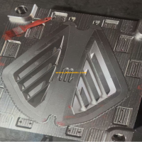
(2) An example of dimension marking for the B board of the moving mold
The structure of the moving die B plate includes: die frame, cooling water circuit, screw holes, push rod (push tube) holes, reset rod holes, holes of the spacing and parting mechanism, and sometimes a lateral core-pulling mechanism, etc. An example of dimension marking is shown in Figure 1-27. The X and Y directions are marked by the coordinate method, with the center line of the mold as the reference. The height dimensions are marked using the linear marking method, with the bottom surface of the template as the reference. Different push rod through holes are represented by different symbols, and their sizes and quantities are listed together
(3) Examples of dimension marking for fixed mold A plates
The marking method for Board A is the same as that for board B
(4) Examples of internal mold insert dimension marking: Generally, insert diagrams are divided into insert screw hole diagrams, cooling water channel diagrams, and insert processing diagrams. The
shape of the insert is simple. The screw holes, cooling water circuit diagram and processing drawing are reflected on the same drawing. Precautions when marking the insert:
1. The direction and reference Angle should be accurately marked on the die side.
2. Express the drawing completely with the fewest views, and mark the dimensions of a shape as clearly as possible on one view.
3. The surfaces that are bumped through and rubbed through should be marked with words.
4. The parting surfaces should be marked according to the positions on the assembly drawing. The reference angles should be specified and the references should be consistent with those on the assembly drawing.
5. For quenched inserts, the draft Angle of the inner mold insert forming surface should be indicated. If the draft Angle of the cavity is 1.5°, the marked size should be the large head (end) size.
ข้อมูลที่เกี่ยวข้อง
จากหลักการสู่การประยุกต์ใช้เข้าใจ "Shaping Master" นี้ในอุตสาหกรรม
2025-07-16
จากหลักการสู่การประยุกต์ใช้เข้าใจ "Shaping Master" นี้ในอุตสาหกรรม P...
รูปแบบ demolding ของแม่พิมพ์สองแผ่น
2025-07-22
ประเภท demolding ของแม่พิมพ์สองแผ่น 1.1 ชิ้นส่วนฉีดยาที่มีการฉีดโดยไม่ต้อง overhan ...

การตั้งค่าอุณหภูมิการฉีดขึ้นรูปและพารามิเตอร์เวลา
2025-07-27
การตั้งค่าอุณหภูมิการฉีดขึ้นรูปและพารามิเตอร์เวลา 1 การตั้งค่าของ TE ...
ลักษณะการทำงานและเกณฑ์การเลือกของแม่พิมพ์ฉีด
2025-06-30
ลักษณะการทำงานและเกณฑ์การเลือกของแม่พิมพ์ฉีดนี้...
สาเหตุและการแก้ปัญหาของฟองสบู่การติดเชื้อราและประตูติดอยู่ในผลิตภัณฑ์แม่พิมพ์ฉีด
2025-07-31
สาเหตุและการแก้ปัญหาของฟองสบู่ติดเชื้อราและประตูติดอยู่ในหัวฉีด ...
พื้นผิวของแม่พิมพ์ถูกอบและพิมพ์สว่างและมีเครื่องหมายการไหลของพื้นผิว
2025-08-02
พื้นผิวของแม่พิมพ์ถูกอบและพิมพ์สว่างและมีเครื่องหมายการไหลของพื้นผิว ...