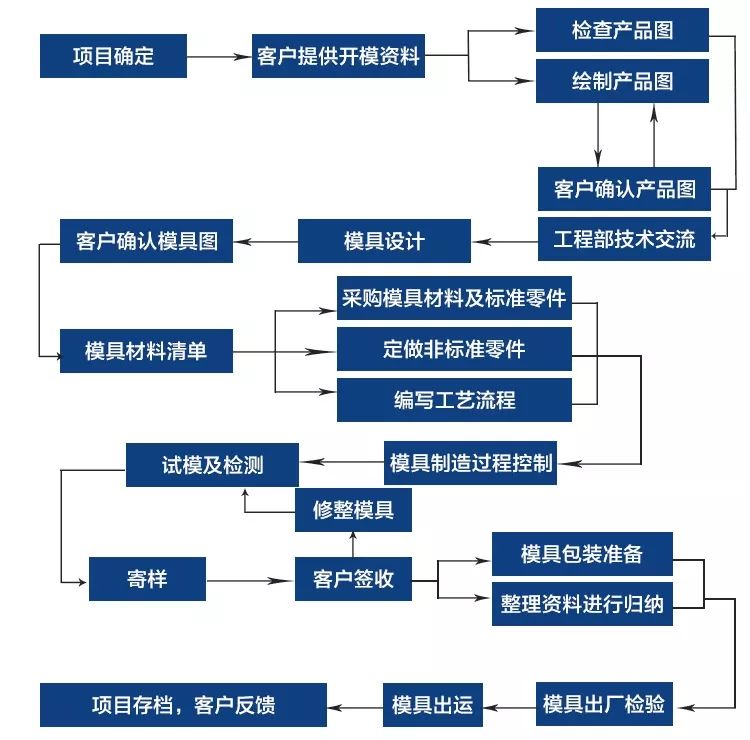
การรวบรวมกระบวนการผลิตแม่พิมพ์มาตรฐานกระบวนการและกรณี
แผนภาพการไหลของกระบวนการมีดังนี้:
ทุกชนิดของเครื่องมือและผลิตภัณฑ์ที่ใช้ในการผลิตประจำวันและชีวิตของเราจากฐานของเครื่องมือเครื่องและเปลือกร่างกายไปยังเปลือกของสกรูหัวตัวอ่อน, ปุ่มและเครื่องใช้ในครัวเรือนต่างๆ, มีความเกี่ยวข้องอย่างใกล้ชิดกับแม่พิมพ์รูปร่างของแม่พิมพ์กำหนดรูปร่างของผลิตภัณฑ์เหล่านี้และคุณภาพและความถูกต้องของแม่พิมพ์ยังกำหนดคุณภาพของผลิตภัณฑ์เหล่านี้เนื่องจากวัสดุที่แตกต่างกันลักษณะข้อกำหนดและการใช้ผลิตภัณฑ์ต่างๆแม่พิมพ์แบ่งออกเป็นแม่พิมพ์ที่ไม่ใช่พลาสติกเช่นแม่พิมพ์หล่อแม่พิมพ์ปลอมแม่พิมพ์หล่อ, แม่พิมพ์ปั๊ม, และแม่พิมพ์พลาสติก
ในช่วงไม่กี่ปีที่ผ่านมาด้วยการพัฒนาอย่างรวดเร็วของอุตสาหกรรมพลาสติกและการปรับปรุงอย่างต่อเนื่องของความแข็งแรงและความแม่นยำของพลาสติกทั่วไปและวิศวกรรมช่วงการใช้งานของผลิตภัณฑ์พลาสติกยังขยายเช่น: เครื่องใช้ในครัวเรือน, เครื่องมือ, อุปกรณ์ก่อสร้าง, อุตสาหกรรมรถยนต์, ฮาร์ดแวร์ประจำวันและสาขาอื่นๆอีกมากมาย, สัดส่วนของผลิตภัณฑ์พลาสติกเพิ่มขึ้นอย่างรวดเร็วชิ้นส่วนพลาสติกที่ออกแบบมาอย่างดีมักจะสามารถเปลี่ยนชิ้นส่วนโลหะแบบดั้งเดิมได้หลายชิ้นแนวโน้มของการทำให้เป็นพลาสติกของผลิตภัณฑ์อุตสาหกรรมและผลิตภัณฑ์ประจำวันเพิ่มขึ้น
1, คำจำกัดความทั่วไปของแม่พิมพ์: ในอุตสาหกรรมการผลิตที่มีความหลากหลายของการกดและเครื่องมือพิเศษที่ติดตั้งอยู่บนกด, ผ่านความดันของโลหะหรือวัสดุที่ไม่ใช่โลหะในการผลิตรูปร่างที่ต้องการของชิ้นส่วนหรือผลิตภัณฑ์เครื่องมือพิเศษนี้จะถูกเรียกรวมว่าแม่พิมพ์
2, กระบวนการฉีดขึ้นรูปคำอธิบาย: แม่พิมพ์เป็นเครื่องมือสำหรับการผลิตผลิตภัณฑ์พลาสติกประกอบด้วยชิ้นส่วนหลายชุดชุดชุดนี้มีช่องขึ้นรูปในระหว่างการฉีดขึ้นรูปแม่พิมพ์จะถูกยึดกับเครื่องฉีดขึ้นรูปพลาสติกหลอมเหลวจะถูกฉีดเข้าไปในช่องแม่พิมพ์และระบายความร้อนและมีรูปร่างในโพรงจากนั้นแม่พิมพ์ด้านบนและด้านล่างจะถูกแยกออกจากกันและผลิตภัณฑ์จะถูกขับออกจากช่องแม่พิมพ์และออกจากแม่พิมพ์ผ่านระบบการดีดออกสุดท้ายแม่พิมพ์จะถูกปิดอีกครั้งสำหรับการฉีดขึ้นรูปต่อไปกระบวนการฉีดขึ้นรูปทั้งหมดจะดำเนินการเป็นวงกลม
3, การจำแนกประเภททั่วไปของแม่พิมพ์: สามารถแบ่งออกเป็นแม่พิมพ์พลาสติกและแม่พิมพ์ที่ไม่ใช่พลาสติก:
1) แม่พิมพ์ที่ไม่ใช่พลาสติกประกอบด้วย: แม่พิมพ์หล่อ, แม่พิมพ์ปลอม, แม่พิมพ์ปั๊ม, แม่พิมพ์หล่อฯลฯ
A. A. หล่อแม่พิมพ์-ก๊อกน้ำ, แพลตฟอร์มเหล็กหมู b. แม่พิมพ์ปลอม-ตัวถังรถ c. แม่พิมพ์ปั๊ม-แผงคอมพิวเตอร์ d. แม่พิมพ์หล่อ-โลหะผสมซุปเปอร์บล็อกกระบอก
2) แม่พิมพ์พลาสติกตามกระบวนการผลิตและการผลิตผลิตภัณฑ์ที่แตกต่างกันจะถูกแบ่ง:
A. A.แม่พิมพ์ฉีดขึ้นรูป-เปลือกทีวีปุ่มคีย์บอร์ด (ใช้กันมากที่สุด) b. แม่พิมพ์เป่าลม-ขวดเครื่องดื่ม c. แม่พิมพ์อัดขึ้นรูป-สวิตช์ Bakelite, ชามพอร์ซเลนทางวิทยาศาสตร์ d. แม่พิมพ์ถ่ายโอนแม่พิมพ์-ผลิตภัณฑ์วงจรรวม e. แม่พิมพ์อัดขึ้นรูป-ท่อกาว, ถุงพลาสติก f. แม่พิมพ์เทอร์โมฟอร์ม-เปลือกบรรจุภัณฑ์ขึ้นรูปโปร่งใส g. แม่พิมพ์ปั้นหมุน-ของเล่นตุ๊กตากาวนุ่ม
แม่พิมพ์ฉีดประกอบด้วยแผ่นเหล็กหลายแผ่นที่มีชิ้นส่วนต่างๆซึ่งแบ่งออกโดยทั่วไป:
อุปกรณ์ปั้น (ตายหญิง, ตายชาย), อุปกรณ์กำหนดตำแหน่ง B (โพสต์คู่มือ, แขนคู่มือ), อุปกรณ์ยึด C (I-PLATE, หลุมตายรหัส), ระบบระบายความร้อน D (รูขนส่งน้ำ), ระบบอุณหภูมิคงที่ E (ท่อความร้อน, ลวดความร้อน), ระบบช่องทางการไหล F (รูหัวฉีด, Flow Channel Groove, flow Channel Hole), G ejection System (ปลอกนิ้ว, Top Stick)
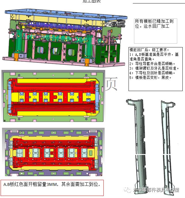
เพื่อให้แน่ใจว่าเหตุผลและความสอดคล้องของการผลิตแม่พิมพ์และเทคโนโลยีการประมวลผลเพิ่มประสิทธิภาพเทคโนโลยีการประมวลผลและปรับปรุงความคืบหน้าของการผลิตแม่พิมพ์, โรงงานแม่พิมพ์แต่ละแห่งโดยทั่วไปจะกำหนดมาตรฐานกระบวนการที่เหมาะสมกับโรงงานกระดาษนี้ให้มาตรฐานอ้างอิง
1.ช่างฝีมือรวบรวมบัตรหัตถกรรม
เมื่อรวบรวมบัตรกระบวนการช่างฝีมือจะระบุรายละเอียดการจองการประมวลผลการวางแนวของการจองความต้องการความหยาบกร้านและเรื่องที่ต้องให้ความสนใจในบัตรกระบวนการ
หลักการเตรียมบัตรกระบวนการประมวลผล: เพื่อให้แน่ใจว่าความถูกต้องและคุณภาพของสถานที่ตั้งความสำคัญคือการใช้อุปกรณ์ที่มีประสิทธิภาพการประมวลผลสูงประสิทธิภาพการประมวลผลของเครื่องกัดซีเอ็นซีและเครื่องบดเร็วกว่าการตัดลวดและชีพจรไฟฟ้าโดยเฉพาะอย่างยิ่งประสิทธิภาพการประมวลผลพัลส์ไฟฟ้าเป็นช้าที่สุดขนาดของภาพวาดไม่สามารถเปลี่ยนแปลงได้ตามต้องการ (เฉพาะช่างเทคนิคเท่านั้นที่สามารถเปลี่ยนแปลงได้)
2.หลักการสำรองในการประมวลผล
สำหรับชิ้นงานที่ต้องการการอบชุบด้วยความร้อนค่าเผื่อเครื่องบด0.25มม. จะถูกเพิ่มที่ด้านหนึ่งของขนาดการเตรียมวัสดุโครงร่างก่อนการอบชุบด้วยความร้อนค่าเผื่อด้านเดียว0.2มม. สงวนไว้สำหรับชิ้นส่วนที่ต้องการการตัดเฉือนหยาบ CNC ของเมล็ดตายและเม็ดมีดค่าเผื่อด้านเดียว0.3-0.5มม. สงวนไว้สำหรับการกัดหยาบของโครงร่างโดยเครื่องกัด fitter, ค่าเผื่อด้านเดียว0.05มม. สงวนไว้สำหรับชิ้นงานที่ต้องการการตัดเฉือนของเครื่องบดหลังจากการตัดลวดและค่าเผื่อการเจียร0.1มม. สงวนไว้สำหรับรูปร่างที่หยาบการตกแต่งซีเอ็นซี, การขัดกระจกหลังจากชีพจรไฟฟ้าให้ค่าเผื่อการขัด0.03มม. ที่ด้านใดด้านหนึ่ง
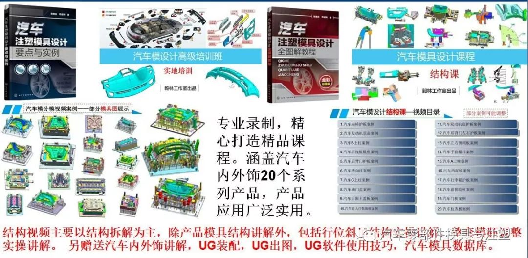
หลักสูตรการออกแบบและโครงสร้างโมเดลรถยนต์: วางจำหน่ายในวันที่1กรกฎาคม
3.ข้อกำหนดความแม่นยำในการตัดเฉือน
ความถูกต้องของการผลิตของขนาดแม่พิมพ์ควรอยู่ในช่วง0.005 ~ 0.02มม. แนวตั้งจะต้องอยู่ในช่วง0.01 ~ 0.02มม. coaxiality จะต้องอยู่ในช่วง0.01 ~ 0.03mm; ความขนานกันของระนาบบนและล่างของพื้นผิวการแยกส่วนตายที่เคลื่อนที่และคงที่จะต้องอยู่ในช่วง0.01 ~ 0.03มม.
หลังจากปิดแม่พิมพ์แล้วช่องว่างระหว่างพื้นผิวที่พรากจากกันจะน้อยกว่าค่าน้ำล้นของพลาสติกขึ้นรูปความขนานของพื้นผิวการผสมพันธุ์เทมเพลตอื่นๆจะต้องอยู่ในช่วง0.01 ~ 0.02มม. ความแม่นยำในการจับคู่ของส่วนคงที่โดยทั่วไปอยู่ในช่วง0.01 ~ 0.02มม. หากไม่มีข้อกำหนดสำหรับการแทรกแกนขนาดเล็กหรืออิทธิพลต่อขนาดไม่ดีควรใช้พิธีการทวิภาคีขนาด0.01 ~ 0.02มม. ความแม่นยำในการจับคู่ของชิ้นส่วนเลื่อนโดยทั่วไปคือ H7/E6 H7/F7และ H7/
หมายเหตุ: หากมีเม็ดมีดที่มีขั้นตอนแขวนอยู่บนพื้นผิวกระจกพอดีไม่ควรแน่นเกินไปมิฉะนั้นเครื่องมือที่ใช้ในการเคาะจะทำให้พื้นผิวกระจกเสียหายได้ง่ายเมื่อใส่กลับจากพื้นผิวด้านหน้าหากขนาดผลิตภัณฑ์ไม่ได้รับผลกระทบระยะห่างระหว่างทั้งสองด้านคือ0.01 ~ 0.02มม.
4.หลักการกำจัดอิเล็กโทรด CNC
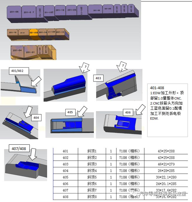
แกนโพรงแม่พิมพ์ควรถอดอิเล็กโทรดหลักที่ปรากฏออกก่อนจากนั้นเอาอิเล็กโทรดหลักอื่นๆออกและสุดท้ายเอาอิเล็กโทรดท้องถิ่นการประมวลผลโดยรวมของอิเล็กโทรดลักษณะแม่พิมพ์คงที่จะต้องได้รับการพิจารณาสำหรับสถานที่ที่ไม่ได้ล้างมุม CNC การตัดลวดจะต้องใช้เพื่อล้างมุมเพื่อให้พื้นผิวลักษณะแม่พิมพ์คงที่เสร็จสมบูรณ์และไม่มีเครื่องหมายร่วมซี่โครงเสริมซี่โครงและเสาที่มีความแตกต่างกันเล็กน้อยในความลึกของแม่พิมพ์ที่เคลื่อนที่สามารถประมวลผลร่วมกันบนขั้วไฟฟ้าหนึ่งตัวให้มากที่สุดและควรเจาะด้านอิเล็กโทรดแยกกันเพื่อป้องกันการสะสมของคาร์บอนระหว่างชีพจรไฟฟ้าไม่ควรตัดอิเล็กโทรดแบบเคลื่อนย้ายได้ด้วยลวดหลังจากการกัด CNC หากจำเป็นควรถอดหรือตัดอิเล็กโทรดด้วยลวดโดยตรงระยะห่างระหว่างซี่โครงและตำแหน่งของแม่พิมพ์ที่เคลื่อนย้ายได้หรือเสาเกิน35มม. ซึ่งควรทำแยกกันเพื่อประหยัดทองแดง
ตำแหน่งประกายไฟที่หยาบด้วยอิเล็กโทรดขนาดใหญ่อยู่ที่0.3มม. ด้านหนึ่งและตำแหน่งประกายไฟตกแต่งอยู่ที่0.15มม. ด้านหนึ่งและตำแหน่งประกายไฟตกแต่งอยู่ที่ด้านหนึ่ง0.1มม. ตำแหน่งประกายไฟหยาบอิเล็กโทรดขนาดเล็กอยู่ที่ด้านหนึ่ง0.15มม. และตำแหน่งจุดประกายการตกแต่งคือ0.07มม. ที่ด้านหนึ่ง
5.หลักการกลึง CNC
หากลักษณะที่ปรากฏของผลิตภัณฑ์อนุญาตให้ใช้แกนโพรงแม่พิมพ์ที่สามารถทำได้โดย CNC เป็นที่ต้องการที่จะกลึงด้วย CNC และหากลักษณะที่ปรากฏของผลิตภัณฑ์อนุญาตแกนโพรงแม่พิมพ์ที่ไม่สามารถทำได้ในสถานที่ที่ผ่านการประมวลผลโดย CNC และถ้าอิเล็กโทรดไม่สามารถประมวลผลได้ในสถานที่, มันถูกประมวลผลโดยชีพจรไฟฟ้า
6.เทคโนโลยีการประมวลผลเคอร์เนลแบบไดนามิกและแบบคงที่
1) การเตรียมวัสดุ
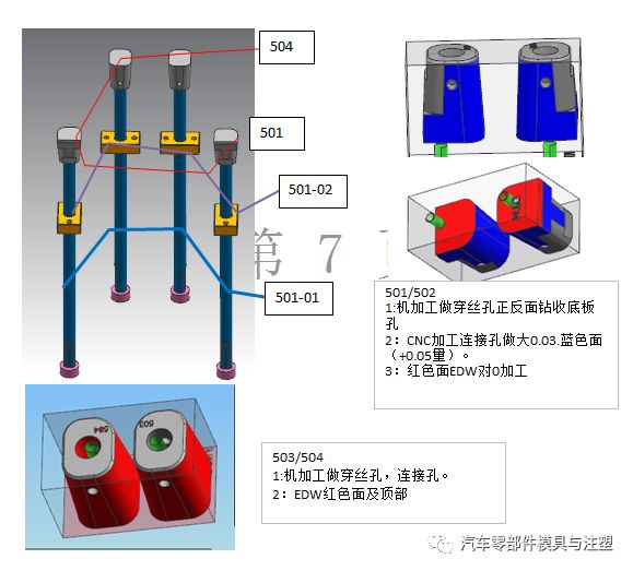
2) การประมวลผลเครื่องกัด: เจาะรูขนส่งน้ำ (ส่วนที่ลึกที่สุดของปลั๊กหลุมขนส่งน้ำอยู่ห่างจากหลุมขนส่งน้ำแนวนอน3-4มม.), หลุมเกลียว, เจาะและแตะรูสกรูเจาะและคว้านรูเข็มจำนวนแม่พิมพ์มุมอ้างอิงและตารางแขวนให้ทาง;
3) เครื่องจักรกลซีเอ็นซี: เครื่องจักรกลหยาบ;
4) การประมวลผลการรักษาความร้อน: ระบุความต้องการความแข็ง;
5) การประมวลผลเครื่องบด: บดสี่เหลี่ยมหกด้าน, รูปร่างที่สอดคล้องกับขนาดเฟรมที่ตรงกัน (ถ้าขนาดรูปร่างของเคอร์เนลแม่พิมพ์หนึ่ง mm-0.05mm กว่าขนาดรูปวาดโดยลบ0.03, ถ้าขนาดรูปร่างของเมล็ดข้าวโพดทั้งสองเป็นสองมิติรูปร่างของเมล็ดข้าวโพดทั้งสองทิศทางรวมกันคือ mm-0.05mm กว่าขนาดการวาดภาพโดยลบ0.03)-0.01,-0.01ส่วนที่สามารถสร้างขึ้นโดยเครื่องบดจะต้องเกิดขึ้น;
6) ถ้าจำเป็นต้องมีการตกแต่ง CNC สำหรับเมล็ดตายจะต้องมีการตกแต่ง CNC หากมีแบบอักษรและตัวเลขตายในโพรงจะต้องใช้ตัวอักษร
7) การประมวลผลการตัดลวด: รูแทรกการประมวลผลลวดขนาดกลาง, รูด้านบนเอียง, รูพินบน, รูหัวฉีดฯลฯ;
8) การตัดเฉือนไฟฟ้า: การตัดเฉือนเดี่ยวตามการวาดและการบ่งชี้ชีพจร;
9) ขัด: เขียนความขรุขระและความต้องการของการขัดบนบัตรไหลของกระบวนการและทำเครื่องหมายพื้นที่ขัดด้วยปากกามาร์กเกอร์บนชิ้นงานหากมีความต้องการกระจกถ้าวงจรสายเกินไปขัดหยาบสามารถดำเนินการก่อนที่จะขัดปรับ;
10) การประกอบ;
11) ทดสอบรุ่น
7.เทคโนโลยีการประมวลผลแทรกร่างกายหลัก
1) การเตรียมวัสดุ: ช่างฝีมือกำหนดว่าจะประมวลผลชิ้นเดียวหรือหลายชิ้นเข้าด้วยกันตามขนาดและรูปร่างของชิ้นงานหากมีการประมวลผลหลายชิ้นเข้าด้วยกันช่างฝีมือจะต้องทำแผนที่การจัดอันดับการประมวลผลของชิ้นงาน
2) การประมวลผลเครื่องกัด: กระบวนการ fitters ตามการวาดภาพชิ้นงานหรือภาพวาดการจัดอันดับที่ผลิตโดยช่างฝีมือ, เจาะรูขนส่งน้ำ (ส่วนที่ลึกที่สุดของปลั๊กรูขนส่งน้ำอยู่ห่างจากรูขนส่งน้ำในแนวนอน3-4มม.) รูเกลียวสว่านและแตะรูสกรูเจาะและรีมรูเข็มด้านบนเปิดส่วนขึ้นรูปประมาณจำนวนแม่พิมพ์และให้วิธีการไปที่โต๊ะแขวน;
3) เครื่องจักรกลซีเอ็นซี: ถ้าชิ้นงานต้องการ CNC หยาบจัด CNC หยาบ;
4) การประมวลผลการรักษาความร้อน: ระบุความต้องการความแข็ง;
5) การประมวลผลเครื่องบด: บดหกด้านตารางส่วนที่สามารถเกิดขึ้นได้โดยเครื่องบดจะต้องพื้นดินและเกิดขึ้น;
6) ถ้าจำเป็นต้องมีการตกแต่ง CNC สำหรับชิ้นงานจะต้องมีการตกแต่ง CNC หากเม็ดมีดมีแบบอักษรและหมายเลขรุ่นต้องใช้ตัวอักษร
7) การประมวลผลการตัดลวด: รูแทรกการประมวลผลลวด, รูด้านบนเอียง, รูพินด้านบนฯลฯ;
8) การตัดเฉือนไฟฟ้า: การตัดเฉือนเดี่ยวตามการวาดและการบ่งชี้ชีพจร;
9) ขัด: เขียนความขรุขระและความต้องการของการขัดบนบัตรไหลของกระบวนการและทำเครื่องหมายพื้นที่ขัดด้วยปากกามาร์กเกอร์บนชิ้นงานหากมีความต้องการกระจกถ้าวงจรสายเกินไปขัดหยาบสามารถดำเนินการก่อนที่จะขัดปรับ;
10) การประกอบ;
11) ทดสอบรุ่น
8.เทคโนโลยีการประมวลผลเม็ดมีดรูปทรงพิเศษ:
กระบวนการที่1
1) การประมวลผลการตัดลวด: การตัดมิติด้านนอกของการตัดลวดกลางมีความแม่นยำ (มุมมอง A/B), แท็บดึง, เครื่องบดที่มีค่าเผื่อความหนาและหนาส่วนขึ้นรูป;
2) การประมวลผลเครื่องบด: ความหนาของการบด, ความลาดชัน, การขึ้นรูป;
3) การตัดเฉือนไฟฟ้า
4) การประมวลผลขัดเงา
กระบวนการ 2:
1) การประมวลผลการตัดลวด: รูปร่างการตัดลวดกลาง, รูแทรก, รูเข็มด้านบน, การตัดขนาด (ดู C), โต๊ะแขวนและการขึ้นรูปที่เปิดหนา;
2) การประมวลผลเครื่องบด: ความสูงของการบด, โต๊ะแขวน, ความลาดชัน, การขึ้นรูป;
3) การตัดเฉือนไฟฟ้า
4) การประมวลผลขัดเงา
9. เทคโนโลยีการประมวลผลแบบแทรกง่าย
1) การประมวลผลการตัดลวด: เครื่องบดการตัดลวดอย่างรวดเร็ว (มุมมอง A/B), แท็บดึง, เครื่องบดค่าเผื่อความหนา;
2) บดขนาดโดยรวมบดโต๊ะแขวนความชันและรูปร่าง
3) การตัดเฉือนไฟฟ้า
4) การประมวลผลขัดเงา
10. เทคโนโลยีการประมวลผลส่วนแทรกกลม
1) การบดที่ไม่ลงรอยกัน: ขนาดโดยรวมของการบด;
2) การประมวลผลเครื่องบด: การทำความสะอาดมุมที่โต๊ะแขวน;
3) การตัดลวด: ความยาวการตัดลวดเร็ว (ค่าเผื่อเครื่องบด 0.1 มม. เหลืออยู่ด้านหนึ่ง) รูเข็มและรูไอเสียจะถูกตัดที่ด้านบน;
4) การประมวลผลเครื่องบด: ความยาวการบด, ขึ้นรูป
11. เทคโนโลยีการประมวลผลชั้นนำที่เอียง
1) การประมวลผลการตัดลวด: รูปร่างการตัดลวดกลางการบดศีรษะด้วยค่าเผื่อการแทรกพื้นผิวบดด้วยค่าเผื่อสำหรับมิติอื่นการบดด้วยค่าเผื่อความหนาของแท็บแบบดึงและเครื่องบดด้วยร่องรูป I;
2) การประมวลผลเครื่องบด: ความหนาของการบด, I-groove;
3) การชุมนุม;
4) พัลส์;
5) การขัด;
6) เครื่องกัดน้ำมันร่องน้ำมัน
12. เทคโนโลยีการประมวลผลของที่นั่งด้านบนสุดเอียง
1) การเตรียมที่ดีขึ้น: 1.5 มม. สำหรับความสูง, 0.5 มม. สำหรับความกว้างและ 5 มม. สำหรับความยาว;
2) การประมวลผลเครื่องกัด: การขุดเจาะและแตะสกรู
3) กระบวนการบำบัดความร้อน
4) การประมวลผลเครื่องบด: การบดสี่เหลี่ยมหกด้าน, การบดขนาดความกว้าง;
5) การตัดลวดการประมวลผลลวดอย่างรวดเร็วร่องรูป I, แท็บดึง, เครื่องบดความหนาความหนา, มิติความสูงคือ 1.2 มม.;
6) การประมวลผลของเครื่องบด: ขนาดเครื่องบดพร้อมแผ่นปลอกไฟขนาดความสูงคือ 1 มม.
13. เทคโนโลยีการประมวลผลของบล็อกคู่มือยอดนิยม
1) การประมวลผลการตัดสาย: รูปร่างการตัดลวดเร็วออกจากเครื่องบดที่สงวนไว้
2) การประมวลผลเครื่องบด: การบดสี่เหลี่ยมหกด้านขนาดโดยรวมของการบด;
3) การประมวลผลเครื่องกัด: รูเกลียว, รูสกรู;
4) การประมวลผลการตัดสาย: การตัดลวดอย่างรวดเร็ว
14. เทคโนโลยีการประมวลผลของที่นั่งสไลด์
1) การเตรียมวัสดุ
2) การประมวลผลเครื่องบด: การบดสี่เหลี่ยมหกด้านขนาดโดยรวมของการบด;
3) การประมวลผลเครื่องกัด: การขุดเจาะรูลวดเจาะรูและแตะสกรู
4) การประมวลผลการตัดลวด: การประมวลผลลวดอย่างรวดเร็วคู่มือเสาเสาเสา;
5) CNC Finishing: การโม่ขนาดของส่วนขึ้นรูป
15. เทคโนโลยีการประมวลผลของ Briquette
1) การเตรียมวัสดุ
2) การประมวลผลเครื่องกัด: เจาะสกรูผ่านรูและเปิดส่วนที่ขึ้นรูป (สงวนไว้ข้างเดียว 0.3-0.5, เครื่องบด);
3) การประมวลผลของเครื่องบด: การบดสี่เหลี่ยมหกด้าน, การบดที่แม่นยำของขนาดภายนอก, การขึ้นรูป
16. เทคโนโลยีการประมวลผลของบล็อกล็อค
1) การเตรียมวัสดุ
2) การประมวลผลเครื่องบด: การบดสี่เหลี่ยมหกด้านขนาดโดยรวมของการบด;
3) การประมวลผลการตัดลวด การขึ้นลวดเร็ว
4) การประมวลผลเครื่องกัด: การเจาะและแตะสกรูรู
17. หลักการตัดเฉือนของหลุมอีเจ็คเตอร์
ด้านบนφ3 (รวมถึงφ3, φ4, φ5, φ6) การประมวลผลหลุมอีเจ็คเตอร์ใช้การเจาะเครื่องกัดและการรีม ด้านล่างφ3หรือหลุมอีเจ็คเตอร์ที่ไม่ได้มาตรฐานการประมวลผลการตัดลวดด้านล่างเพื่อหลีกเลี่ยงความว่างเปล่า
18. หลักการประมวลผลรูลวด
เมื่อรูทุกชนิดต้องถูกประมวลผลโดยการตัดลวดเมื่อเส้นรอบวงของผนังด้านในมากกว่าφ3 (รวมถึงφ3) รูลวดจะต้องเจาะ
19. การประมวลผลของเครื่องหมายการค้าและความจำเป็นในการโยนแม่พิมพ์กระจก
1) ค่าเผื่อจะถูกทิ้งไว้ที่เครื่องหมายการค้าหลังจาก CNC เสร็จสิ้นการกัดเคอร์เนลแม่พิมพ์;
2) การประมวลผลลวดกลางลวด: รูแทรกเครื่องหมายการค้าหลุม;
3) การตัดเฉือนไฟฟ้า: ความลึกของตารางแขวนนั้นแม่นยำ
4) ติดตั้ง Core เครื่องหมายการค้าและติดตั้งติดตั้ง;
5) ชีพจรที่เหลืออยู่ที่เครื่องหมายการค้าจะถูกปรับระดับ ⑥ขัด
20. เทคโนโลยีการประมวลผลฐานแม่พิมพ์
1) การประมวลผลเครื่องกัด: การลบล้างกรอบด้านในรูสกรูเจาะรูพินด้านบนหลุมทางน้ำถ้วยประตูผ่านรูและรูด้านบนเอียงผ่านรู;
2) การตัดเฉือนซีเอ็นซี: การกัดถ้วยถ้วยเคาน์เตอร์, รูเบาะด้านบนเอียง, หลุมบล็อกคู่มือ, ร่องแถว, จานแม่พิมพ์ร้อนที่ต้องการการตัดเฉือนซีเอ็นซี, การประมวลผลการแกะสลักเท้าแม่พิมพ์
21. เทคโนโลยีการประมวลผลหลังการติดตั้งของกรอบการติดตั้งด้วยซี่โครงเสริมแบบกริด
กรอบการติดตั้งชนิดนี้หลังจากการประมวลผลตำแหน่งซี่โครงแม่พิมพ์ตามหมวดหมู่แม่พิมพ์ที่แตกต่างกันเลือกเทคโนโลยีการประมวลผลที่แตกต่างกัน
1) เราใช้อิเล็กโทรดทั้งหมดโดยตรงสำหรับแม่พิมพ์ประเภทหนึ่งเพื่อให้แน่ใจว่าเป็นเอกภาพของผลิตภัณฑ์
2) เมื่อเลือกเทคโนโลยีการประมวลผลของแม่พิมพ์ที่ไม่ใช่ประเภทจะถูกจัดสรรตามจำนวนการประมวลผลจริง อิเล็กโทรดสามารถแบ่งหรือรวมเข้าด้วยกัน หากตำแหน่งซี่โครงผ่านร่องลวดสามารถตัดหนาได้ก่อนแล้วเครื่องบดสามารถปรับแต่งได้
22. ต้องการการติดตั้งสายไฟหรืออิเล็กโทรด, ชิ้นงานพัลส์แบทช์
สำหรับชิ้นงานบางชิ้น (เช่นแกนกลางของซ็อกเก็ตสองฟังก์ชั่นแบบมัลติฟังก์ชั่น) จำเป็นต้องใช้การติดตั้งลวดหรืออิเล็กโทรด การประมวลผลการไหลของชิ้นงานพัลส์แบทช์มีดังนี้:
1) CNC ออกจากแผนภูมิการจัดอันดับ;
2) การวาดการตัดลวดตามขนาดของอุปกรณ์ติดตั้งหรืออิเล็กโทรด
3) หลังจากกระบวนการตัดลวดเสร็จสมบูรณ์หากขั้วไฟฟ้าจำเป็นต้องดำเนินการ CNC อิเล็กโทรดจะถูกส่งไปยัง CNC และการติดตั้งจะถูกส่งไปยังช่างฟิต;
4) อิเล็กโทรดการตัดเฉือน CNC และไดอะแกรมการปลดปล่อย;
5) การตัดเฉือนชีพจร;
6) การขัด
23. การคำนวณความสูงของคอลัมน์สนับสนุน
ความสูงของคอลัมน์สนับสนุนด้านล่าง 3030 ของแบบหล่อสูงกว่า 0.08-0.1 มม. สูงกว่าเท้าแบบหล่อสูงกว่า 0.1 มม. สูงกว่า 3030, 0.1-0.12 มม. สูงกว่า 3535 และ 0.12-0.15 มม. สูงกว่า 3535
24. เทคโนโลยีการประมวลผล Thimble
φ 2 และสูงกว่าเครื่องตัดปลอกเครื่องตัดความยาวการตัดค่าเผื่อการบดเครื่องบดเครื่องบดการประมวลผลขนาดการบด (การประมวลผลของตัวเองที่น่าพอใจ); ขนาดการประมวลผลการตัดลวดปลอกไฟต่ำกว่าφ 2 นั้นแม่นยำ ปลอกนิ้วมือและกระบอกสูบจะต้องทำโดยเครื่องบดความยาวการตัดลวด เครื่องบดจะต้องใช้สำหรับการประมวลผลและความยาวและมิติจะต้องเป็นพื้นอย่างแม่นยำ
1. EDM
(1) หลักการพื้นฐาน
EDM เป็นวิธีการประมวลผลพิเศษที่ใช้การพังทลายของไฟฟ้าที่เกิดจากการปล่อยพัลส์ระหว่างขั้วทั้งสองที่แช่อยู่ในของเหลวที่ทำงานเพื่อกำจัดวัสดุนำไฟฟ้าหรือที่เรียกว่าการตัดเฉือนหรือการตัดเฉือนไฟฟ้า
(2) อุปกรณ์พื้นฐาน: เครื่องมือเครื่อง EDM
(3) คุณสมบัติหลัก
สามารถประมวลผลวัสดุและชิ้นงานที่มีรูปร่างที่ซับซ้อนซึ่งยากที่จะตัดด้วยวิธีการตัดธรรมดา ไม่มีแรงตัดในระหว่างการประมวลผล ไม่มีการสร้างรอย, เครื่องหมายเครื่องมือ, ร่องและข้อบกพร่องอื่น ๆ วัสดุอิเล็กโทรดเครื่องมือไม่จำเป็นต้องยากกว่าวัสดุชิ้นงาน การใช้พลังงานไฟฟ้าโดยตรงสำหรับการประมวลผลนั้นสะดวกสำหรับระบบอัตโนมัติ หลังจากการประมวลผลเลเยอร์ metamorphic จะถูกสร้างขึ้นบนพื้นผิวซึ่งจะต้องลบออกเพิ่มเติมในบางแอปพลิเคชัน การทำให้บริสุทธิ์ของของเหลวในการทำงานและการรักษามลพิษควันที่เกิดขึ้นในการแปรรูปมีปัญหามากขึ้น
(4) ขอบเขตการใช้งาน
การประมวลผลแม่พิมพ์และชิ้นส่วนที่มีรูปร่างที่ซับซ้อนของรูและโพรง การประมวลผลวัสดุที่แข็งและเปราะต่าง ๆ เช่นโลหะผสมแข็งและเหล็กแข็ง การประมวลผลหลุมละเอียดลึก, หลุมที่มีรูปร่างพิเศษ, ร่องลึก, ร่องแคบและแผ่นตัด ฯลฯ การประมวลผลเครื่องมือสร้างต่าง ๆ เทมเพลตชุดเกจแหวนด้ายและเครื่องมืออื่น ๆ และเครื่องมือวัด
2. Wedm
(1) หลักการพื้นฐาน
การใช้ลวดโลหะบาง ๆ ที่เคลื่อนที่อย่างต่อเนื่อง (เรียกว่าลวดอิเล็กโทรด) เป็นอิเล็กโทรด, ชิ้นงานพัลส์พัลส์การสึกกร่อนเพื่อกำจัดโลหะการตัดและการขึ้นรูป ภาษาอังกฤษสำหรับการตัดการตัดเฉือนไฟฟ้าแบบตัดสายไฟเรียกว่า Wedm หรือที่เรียกว่าการตัดลวด
(2) อุปกรณ์พื้นฐาน: เครื่องมือเครื่อง Wedm
(3) คุณสมบัติหลัก
Wedm นอกเหนือจากลักษณะพื้นฐานของ EDM แล้วยังมีคุณสมบัติอื่น ๆ :
①ไม่จำเป็นต้องผลิตอิเล็กโทรดเครื่องมือที่มีรูปร่างที่ซับซ้อนเพื่อประมวลผลพื้นผิวสองมิติใด ๆ ที่มีเส้นตรงเป็น generatrix;
②สามารถตัดร่องแคบ ๆ ประมาณ 0.05 มม.;
ในกระบวนการวัสดุส่วนเกินทั้งหมดจะไม่ถูกประมวลผลเป็นชิปของเสียซึ่งช่วยเพิ่มอัตราการใช้พลังงานและวัสดุ
④ในกระบวนการ EDM ลวดความเร็วต่ำซึ่งไม่ได้รีไซเคิลลวดอิเล็กโทรดลวดอิเล็กโทรดได้รับการปรับปรุงอย่างต่อเนื่องซึ่งเป็นประโยชน์ในการปรับปรุงความแม่นยำในการตัดเฉือนและลดความขรุขระของพื้นผิว
⑤ประสิทธิภาพการตัดที่ทำได้โดย WEDM โดยทั่วไปคือ 20-60 มม. 2/นาทีสูงสุด 300 มม. 2/นาที ความแม่นยำของการตัดเฉือนโดยทั่วไป± 0.01 ถึง± 0.02 มม. สูงถึง± 0.004 มม.; ความขรุขระพื้นผิวโดยทั่วไปคือ RA2.5 ถึง 1.25 ไมครอนสูงถึง RA0.63 ไมครอน ความหนาของการตัดโดยทั่วไปคือ 40-60 มม. และความหนาสูงสุดสามารถถึง 600 มม.
(4) ขอบเขตการใช้งาน
ส่วนใหญ่ใช้สำหรับการประมวลผล: รูปทรงที่ซับซ้อนและชิ้นงานขนาดเล็กที่มีความแม่นยำเช่นหมัดหมัดหมัดตาย, หมัด, แผ่นคงที่, แผ่นปล่อย, ฯลฯ ; เครื่องมือสร้าง, เทมเพลต, EDM สร้างอิเล็กโทรดโลหะ; ความหลากหลายของหลุมขนาดเล็ก, ร่องแคบ, เส้นโค้งโดยพลการ มันมีข้อได้เปรียบที่โดดเด่นของค่าเผื่อการตัดเฉือนขนาดเล็กความแม่นยำของการตัดเฉือนสูงรอบการผลิตระยะสั้นและต้นทุนการผลิตต่ำและมีการใช้กันอย่างแพร่หลายในการผลิต ในปัจจุบันเครื่องมือ Wedm Machine ทั้งที่บ้านและต่างประเทศคิดเป็นมากกว่า 60% ของจำนวนเครื่องมือ EDM ทั้งหมด
3. การตัดเฉือนอิเล็กโทรไลต์ (เครื่องจักรเคมีไฟฟ้า)
(1) หลักการพื้นฐาน
ขึ้นอยู่กับหลักการของการสลายตัวของขั้วบวกในกระบวนการอิเล็กโทรไลต์และด้วยความช่วยเหลือของแคโทดที่เกิดขึ้นชิ้นงานจะถูกประมวลผลเป็นรูปร่างและขนาดที่แน่นอนเรียกว่าการประมวลผลอิเล็กโทรไลต์
(2) ขอบเขตการใช้งาน
การตัดเฉือนทางเคมีไฟฟ้ามีข้อดีอย่างมีนัยสำคัญสำหรับการตัดเฉือนของวัสดุที่ยากต่อเครื่องจักรรูปร่างที่ซับซ้อนหรือชิ้นส่วนผนังบาง เครื่องจักรกลอิเล็กทรอนิกส์ถูกนำมาใช้อย่างกว้างขวางเช่นปืนไรเฟิลบาร์เรลใบมีดใบพัดอินทิกรัลแม่พิมพ์รูรูปพิเศษและชิ้นส่วนที่มีรูปร่างพิเศษการตัดแต่งและการหักล้าง และในการประมวลผลของหลายส่วนกระบวนการเครื่องจักรกลอิเล็กโทรไลต์ได้ครอบครองตำแหน่งที่สำคัญและไม่สามารถถูกแทนที่ได้
(3) ข้อดี
การประมวลผลที่หลากหลาย เครื่องจักรกลอิเล็กโทรไลต์สามารถประมวลผลวัสดุนำไฟฟ้าได้เกือบทั้งหมดและไม่ถูก จำกัด ด้วยคุณสมบัติเชิงกลและทางกายภาพเช่นความแข็งแรงความแข็งและความทนทานของวัสดุและโครงสร้างโลหะของวัสดุหลังจากการประมวลผลโดยทั่วไปจะไม่เปลี่ยนแปลง มันมักจะใช้ในการประมวลผลโลหะผสมแข็งโลหะผสมอุณหภูมิสูงเหล็กแข็งสแตนเลสและวัสดุที่ยากต่อการประมวลผลอื่น ๆ
(4) ข้อ จำกัด
ความแม่นยำในการตัดเฉือนและความเสถียรในการประมวลผลไม่สูงค่าใช้จ่ายในการประมวลผลจะสูงขึ้นและยิ่งแบทช์เล็กลงเท่าใดค่าใช้จ่ายเพิ่มเติมของชิ้นเดียว
4. การประมวลผลด้วยเลเซอร์
(1) หลักการพื้นฐาน
การประมวลผลด้วยเลเซอร์คือการใช้พลังงานแสงผ่านเลนส์มุ่งเน้นไปที่โฟกัสเพื่อให้ได้ความหนาแน่นของพลังงานสูงในเวลาที่น้อยมากในการละลายหรือทำให้เป็นไอวัสดุและถูกจารึกลงเพื่อให้ได้การประมวลผล
(2) คุณสมบัติหลัก
เทคโนโลยีการประมวลผลด้วยเลเซอร์มีข้อดีของเสียวัสดุน้อยลงผลค่าใช้จ่ายที่ชัดเจนในการผลิตขนาดใหญ่และการปรับตัวที่แข็งแกร่งกับวัตถุการประมวลผล ในยุโรปการเชื่อมของวัสดุพิเศษเช่นเปลือกหอยรถยนต์ระดับสูงและฐานปีกเครื่องบินและยานอวกาศฟาเซลิจเป็นเทคโนโลยีเลเซอร์โดยทั่วไป
(3) ขอบเขตการใช้งาน
การประมวลผลด้วยเลเซอร์เป็นแอปพลิเคชันที่ใช้กันมากที่สุดของระบบเลเซอร์ เทคโนโลยีหลัก ได้แก่ : การเชื่อมด้วยเลเซอร์, การตัดด้วยเลเซอร์, การดัดแปลงพื้นผิว, การทำเครื่องหมายเลเซอร์, การขุดเจาะด้วยเลเซอร์, การดูดซับขนาดเล็กและการสะสมโฟโตเคมี, stereolithography, เลเซอร์แกะสลักและอื่น ๆ
5. การตัดเฉือนของลำแสงอิเล็กตรอน
(1) หลักการพื้นฐาน
การตัดเฉือนของลำแสงอิเล็กตรอนคือการตัดเฉือนของวัสดุโดยใช้ผลกระทบความร้อนหรือไอออนไนซ์ของคานอิเล็กตรอนที่มาบรรจบกันพลังงานสูง
(2) คุณสมบัติหลัก
ความหนาแน่นของพลังงานสูงความสามารถในการเจาะทะลุที่แข็งแกร่งการเจาะขั้นต้นที่หลากหลายอัตราส่วนความกว้างเชื่อมขนาดใหญ่ความเร็วการเชื่อมที่รวดเร็วโซนที่ได้รับผลกระทบจากความร้อนขนาดเล็กและการเสียรูปขนาดเล็ก
(3) ขอบเขตการใช้งาน
การประมวลผลลำแสงอิเล็กตรอนของวัสดุที่หลากหลายพื้นที่การประมวลผลอาจมีขนาดเล็กมาก ความแม่นยำในการประมวลผลสามารถไปถึงระดับนาโนเมตรเพื่อให้ได้การประมวลผลระดับโมเลกุลหรืออะตอม ผลผลิตสูง การประมวลผลมลพิษเล็ก ๆ แต่ค่าใช้จ่ายในการประมวลผลที่สูง สามารถประมวลผล micropores ตะเข็บแคบ ฯลฯ แต่ยังสามารถใช้สำหรับการเชื่อมและการพิมพ์หินละเอียด เทคโนโลยีการเชื่อมลำแสงอิเล็กตรอนสูญญากาศเป็นแอพพลิเคชั่นหลักของการประมวลผลลำแสงอิเล็กตรอนในอุตสาหกรรมการผลิตรถยนต์
6. การตัดเฉือนไอออนลำแสง
(1) หลักการพื้นฐาน
การประมวลผลลำแสงไอออนอยู่ในสถานะสุญญากาศลำธารไอออนที่สร้างขึ้นโดยแหล่งไอออนจะถูกเร่งและมุ่งเน้นไปที่พื้นผิวของชิ้นงานเพื่อให้ได้การประมวลผล
(2) คุณสมบัติหลัก
เนื่องจากความหนาแน่นของกระแสไอออนและพลังงานไอออนสามารถควบคุมได้อย่างแม่นยำเอฟเฟกต์การประมวลผลจึงสามารถควบคุมได้อย่างแม่นยำและการประมวลผลความแม่นยำเป็นพิเศษที่ระดับนาโนและแม้แต่ในระดับโมเลกุลและอะตอมสามารถรับรู้ได้ ในระหว่างการประมวลผลลำแสงไอออนมลพิษที่เกิดขึ้นมีขนาดเล็กความเครียดจากการประมวลผลและการเสียรูปมีขนาดเล็กมากและความสามารถในการปรับตัวให้เข้ากับวัสดุที่ประมวลผลนั้นแข็งแกร่ง แต่ค่าใช้จ่ายในการประมวลผลสูง
(3) ขอบเขตการใช้งาน
การประมวลผลลำแสงไอออนสามารถแบ่งออกเป็นการแกะสลักและการเคลือบตามวัตถุประสงค์
1) การแปรรูปการแกะสลัก
การแกะสลักไอออนใช้ในการประมวลผลร่องบนแบริ่งอากาศของไจโรสโคปและมอเตอร์แรงดันแบบไดนามิกที่มีความละเอียดสูงความแม่นยำและการทำซ้ำที่ดี อีกแง่มุมหนึ่งของแอพพลิเคชั่นการแกะสลักไอออนคานคือการแกะสลักกราฟิกที่มีความแม่นยำสูงเช่นส่วนประกอบอิเล็กทรอนิกส์เช่นวงจรรวมอุปกรณ์ออพโตอิเล็กทรอนิกส์และอุปกรณ์รวมแบบออพติคอล การแกะสลักลำแสงไอออนยังใช้กับวัสดุบาง ๆ และทำชิ้นส่วนทดสอบกล้องจุลทรรศน์อิเล็กตรอนแบบเจาะ
2) การประมวลผลการเคลือบไอออนคาน
การประมวลผลการเคลือบไอออนลำแสงมีสองรูปแบบ: การสะสมสปัตเตอร์และการชุบไอออน การชุบไอออนสามารถเป็นวัสดุที่หลากหลายโดยไม่คำนึงถึงโลหะพื้นผิวที่ไม่ใช่โลหะสามารถชุบโลหะหรือฟิล์มที่ไม่ใช่โลหะโลหะผสมสารประกอบหรือวัสดุสังเคราะห์บางชนิดวัสดุเซมิคอนดักเตอร์
เทคโนโลยีการเคลือบไอออนลำแสงสามารถใช้สำหรับการเคลือบฟิล์มหล่อลื่นฟิล์มทนความร้อนฟิล์มที่ทนต่อการสวมใส่ฟิล์มตกแต่งและฟิล์มไฟฟ้า
7. การประมวลผลส่วนโค้งพลาสมา
(1) หลักการพื้นฐาน
การประมวลผลส่วนโค้งพลาสมาเป็นวิธีการประมวลผลพิเศษที่ใช้พลังงานความร้อนของส่วนโค้งพลาสมาเพื่อตัดเชื่อมและสเปรย์โลหะหรือไม่ใช่โลหะ
(2) คุณสมบัติหลัก
1) การเชื่อมส่วนโค้ง micro-plasma สามารถเชื่อมฟอยล์และแผ่น
2) ด้วยเอฟเฟกต์รูเล็ก ๆ สามารถบรรลุการเชื่อมแบบสองด้านได้ดีขึ้น
3) ความหนาแน่นของพลังงานอาร์คพลาสมา, อุณหภูมิคอลัมน์อาร์คสูง, ความสามารถในการเจาะที่แข็งแกร่ง, เหล็กหนา 10-12 มม. ไม่สามารถเปิดร่อง, สามารถเป็นรูปแบบสองด้าน, ความเร็วในการเชื่อม, การผลิตสูง, การเปลี่ยนรูปความเครียดขนาดเล็ก;
4) อุปกรณ์มีความซับซ้อนมากขึ้นการใช้ก๊าซมีขนาดใหญ่เหมาะสำหรับการเชื่อมในร่มเท่านั้น
(3) ขอบเขตการใช้งาน
ใช้กันอย่างแพร่หลายในการผลิตอุตสาหกรรมโดยเฉพาะอย่างยิ่งในการบินและอวกาศและเทคโนโลยีทางทหารอื่น ๆ และเทคโนโลยีอุตสาหกรรมที่ทันสมัยที่ใช้ในการเชื่อมของโลหะผสมทองแดงและทองแดง, ไทเทเนียมและโลหะผสมไทเทเนียม, เหล็กกล้าอัลลอยด์, สแตนเลส, โมลิบดีนัมและโลหะอื่น ๆ
8. การตัดเฉือนอัลตราโซนิก
(1) หลักการพื้นฐาน
การตัดเฉือนอัลตราโซนิกคือการใช้ความถี่อัลตราโซนิกสำหรับการสั่นสะเทือนขนาดเล็กของเครื่องมือและผ่านมันและชิ้นงานฟรีในของเหลวระหว่างการกัดกร่อนบนพื้นผิวที่จะประมวลผลโดยเอฟเฟกต์การตอกเพื่อให้พื้นผิวชิ้นงานชิ้นงานแตกหัก การตัดเฉือนอัลตราโซนิกมักจะใช้สำหรับการเจาะตัดการเชื่อมการทำรังและการขัด
(2) คุณสมบัติหลัก
มันสามารถประมวลผลวัสดุใด ๆ ที่เหมาะสมโดยเฉพาะอย่างยิ่งสำหรับการประมวลผลของวัสดุที่ไม่ได้รับการศึกษาที่แข็งและเปราะ ความแม่นยำในการประมวลผลของชิ้นงานสูงคุณภาพพื้นผิวดี แต่ผลผลิตต่ำ
(3) ขอบเขตการใช้งาน
การตัดเฉือนอัลตราโซนิกส่วนใหญ่จะใช้สำหรับวัสดุที่แข็งและเปราะเช่นแก้ว, ควอตซ์, เซรามิก, ซิลิคอน, เจอร์เมเนียม, เฟอร์ไรต์, หินมีค่าและหยก ฯลฯ (รวมถึงรูกลม, หลุมรูปทรงพิเศษ
9. การประมวลผลทางเคมี
(1) หลักการพื้นฐาน
การประมวลผลทางเคมี (การแกะสลักทางเคมี) คือการใช้กรดอัลคาไลหรือสารละลายเกลือในการละลายของวัสดุชิ้นงานเพื่อให้ได้รูปร่างขนาดหรือสถานะพื้นผิวของการประมวลผลพิเศษชิ้นงาน
(2) คุณสมบัติหลัก
1) สามารถประมวลผลวัสดุโลหะตัดใด ๆ ไม่ จำกัด ด้วยความแข็งความแข็งแรงและคุณสมบัติอื่น ๆ
2) เหมาะสำหรับการประมวลผลพื้นที่ขนาดใหญ่และสามารถประมวลผลหลายชิ้นในเวลาเดียวกัน
3) ไม่มีความเครียด, รอยแตก, เสี้ยน, ความขรุขระของพื้นผิวของ Ra1.25-2.5 μm;
4) การใช้งานง่าย
5) ไม่เหมาะสำหรับการประมวลผลช่องและรูแคบ
6) ไม่แนะนำให้กำจัดข้อบกพร่องเช่นพื้นผิวที่ไม่สม่ำเสมอและรอยขีดข่วน
(3) ขอบเขตการใช้งาน
เหมาะสำหรับการประมวลผลการลดความหนาของพื้นที่ขนาดใหญ่ เหมาะสำหรับการประมวลผลหลุมที่ซับซ้อนในชิ้นส่วนที่มีผนังบาง
ข้อมูลที่เกี่ยวข้อง
การสำรวจแม่พิมพ์ฉีด: รากฐานความแม่นยำของอุตสาหกรรมการผลิต
2025-07-11
สำรวจแม่พิมพ์ฉีด: รากฐานความแม่นยำของอุตสาหกรรมการผลิต...
เคสแม่พิมพ์รวมเส้นและสีขาวที่เปิดเผย
2025-08-04
เคสแม่พิมพ์รวมเส้นและเส้นสีขาวที่เปิดเผย: ปรากฏการณ์: The ...
กระบวนการทั่วไปของการออกแบบแม่พิมพ์และการวาดภาพ
2025-09-08
กระบวนการทั่วไปของการออกแบบแม่พิมพ์และการวาดภาพ: จัดระเบียบและตรวจสอบลูกค้า ...

ส่วนมาตรฐานของแม่พิมพ์
2025-07-24
ชิ้นส่วนมาตรฐานของ Molds1 Mold FramePrefabricated Assemblies ฐานแม่พิมพ์มาตรฐาน o ...
เทคโนโลยีประตูแม่พิมพ์ฉีด
2025-07-23
Injection Mold Gate TechnologyGating Systemauto Mould_taizhou Jiefeng Mold Co., ...
ตำแหน่งทางเข้ากาวของแม่พิมพ์ถูกลากและไหม้เกรียม
2025-08-06
ตำแหน่งทางเข้าของกาวของแม่พิมพ์ถูกลากและตะโกนกาวทางเข้าของ ...