จำกัด พินและสปริงของแม่พิมพ์
จำกัด พินและสปริงของแม่พิมพ์
หนึ่ง: จำกัด พิน
ฟังก์ชั่นของเล็บขีด จำกัด คือการสร้างช่องว่างบางอย่างระหว่างแผ่นก้านกดและแผ่นด้านล่างของแม่พิมพ์ที่เคลื่อนที่ป้องกันการเสียรูปของแม่แบบหรือการเชื่อมต่อระหว่างแผ่นก้านและแม่พิมพ์ที่เคลื่อนที่
ขยะอยู่ระหว่างแผ่นด้านล่างของแม่พิมพ์ทำให้แผ่นก้านดันไม่สามารถรีเซ็ตได้อย่างถูกต้อง จำกัด เล็บซึ่งเป็นที่รู้จักกันทั่วไปว่าเป็นเล็บขยะมักทำจากวัสดุ P-20
(1) ข้อกำหนดและแบบจำลองของ PIN จำกัด
มีสองรูปร่างมาตรฐานของหมุด จำกัด
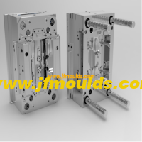
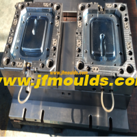
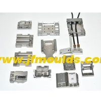
ผู้ผลิตโคมไฟรถยนต์ในประเทศจีน (jfmoulds.com)

(2) ขนาดของพินขีด จำกัด
(3) การประกอบเล็บ จำกัด
ควรติดตั้งพินขีด จำกัด บนแผ่นฐานของแม่พิมพ์ที่เคลื่อนที่ สำหรับพิน จำกัด อินทิกรัลควรใช้ความพอดีสัญญาณรบกวน
②ตำแหน่งของพินขีด จำกัด ควรเพิ่มเล็บ จำกัด ภายใต้แท่งรีเซ็ตทั้งหมดที่พื้นที่หนาแน่นของแท่งดันและภายใต้แท่งดันเอียงเพื่อทนต่อแรงขยายตัวในระหว่างการฉีดแม่พิมพ์
สอง: ฤดูใบไม้ผลิ

ในแม่พิมพ์สปริงส่วนใหญ่จะใช้เป็นพลังงานเสริมสำหรับการเคลื่อนย้ายส่วนประกอบเช่นการรีเซ็ตของแผ่นก้านดันการวางตำแหน่งของตัวเลื่อนในกลไกการดึงแกนด้านข้างและระยะห่างและการแยกเทมเพลตที่เคลื่อนย้ายได้ เนื่องจากสปริงขาดแรงผลักดันที่เข้มงวดและมีแนวโน้มที่จะเกิดความเหนื่อยล้าพวกเขาจึงไม่ได้รับอนุญาตให้ใช้เพียงอย่างเดียว
ใช้. สปริงในแม่พิมพ์รวมถึงสปริงสีน้ำเงินสี่เหลี่ยมและสปริงสีดำวงกลม เนื่องจากสปริงสีน้ำเงินสี่เหลี่ยมมีค่าสัมประสิทธิ์ยืดหยุ่นมากขึ้นความแข็งแกร่งที่แข็งแกร่งและอัตราส่วนการบีบอัดที่ใหญ่กว่าสปริงสีดำแบบวงกลมสปริงสีน้ำเงินสี่เหลี่ยมจึงใช้ในแม่พิมพ์
(1) สปริงรีเซ็ตแผ่นก้านดัน
ดันแผ่นก้านดันกลับไปยังตำแหน่งเดิม สปริงรีเซ็ตที่ใช้กันทั่วไปคือสปริงสีน้ำเงินสี่เหลี่ยม แต่ถ้าแม่พิมพ์มีขนาดใหญ่และมีแท่งดันจำนวนมากมันจะต้องเป็น
พิจารณาใช้สปริงสี่เหลี่ยมสีเขียวหรือสีกาแฟ เมื่อเลือกภาพขนาดย่อโหลดเบาควรสังเกตด้านต่อไปนี้
1. จำนวนเงินล่วงหน้าและอัตราส่วนการโหลดล่วงหน้า
เมื่อแผ่นก้านกดกลับไปยังตำแหน่งเดิมสปริงยังคงต้องรักษาแรงยืดหยุ่นบนแผ่นก้านดัน แรงนี้มาจากแรงดันสูงสุดของสปริงและโดยทั่วไปแล้วแรงดันล่วงหน้าจะต้องอยู่ที่ประมาณ 10% ของความยาวอิสระของสปริง
จำนวนเงินล่วงหน้าหารด้วยความยาวฟรีให้อัตราส่วนล่วงหน้า สำหรับสปริงที่มีเส้นผ่านศูนย์กลางใหญ่กว่าควรเลือกอัตราส่วนล่วงหน้าที่เล็กลง
เมื่อเลือกสปริงส่งคืนสำหรับแผ่นก้านดันแม่พิมพ์อัตราส่วนล่วงหน้าจะไม่ถูกใช้โดยทั่วไป แต่จะใช้จำนวนเงินล่วงหน้าโดยตรง สิ่งนี้สามารถมั่นใจได้ว่าภายใต้เงื่อนไขของขนาดเส้นผ่านศูนย์กลางสปริงที่สอดคล้องกันการโหลดล่วงหน้าที่ใช้กับแผ่นก้านดันไม่ได้รับผลกระทบจากความยาวอิสระของสปริง การโหลดล่วงหน้าโดยทั่วไปจะใช้เป็น 10.0 ถึง 15.0 มม.
2. ปริมาณการบีบอัดและอัตราส่วนการบีบอัด
สปริงบีบอัดมักใช้ในแม่พิมพ์ เมื่อแผ่นก้านกดดันชิ้นส่วนพลาสติกออกมาสปริงจะถูกบีบอัดและปริมาณการบีบอัดเท่ากับระยะทางที่ส่วนพลาสติกจะถูกผลักออก อัตราส่วนการบีบอัดคืออัตราส่วนของจำนวนการบีบอัดต่อความยาวอิสระ โดยทั่วไปตามข้อกำหนดของอายุการใช้งานอัตราส่วนการบีบอัดของสปริงสีน้ำเงินสี่เหลี่ยมอยู่ระหว่าง 30% ถึง 40% อัตราส่วนการบีบอัดที่เล็กลงยิ่งอายุการใช้งานนานขึ้นเท่านั้น
3. จำนวนและเส้นผ่านศูนย์กลางของสปริงรีเซ็ต
4. การกำหนดความยาวอิสระของสปริง
① Free length calculation: The free length of the spring should be determined based on the compression ratio and the required compression amount. In the formula L free =(E P)/S
E is the stroke of the push rod plate, E= the minimum distance the plastic part is pushed out 15 to 20mm.
P represents the preload amount, which is generally taken as 10 to 15mm. It is determined based on the resistance during reset. The smaller the resistance, the smaller the preload. Usually, it can also be selected according to the size of the mold frame. For mold frames 3030(inclusive) or less, the preload amount is 5mm; for mold frames 3030 or more, the compression amount is 10 to 15mm.
S represents the compression ratio, typically taken as 30% to 40%. The free length should be determined based on factors such as mold life, mold size, and the distance between plastic parts. The standard length should be taken upwards.
If the calculated length is greater than the minimum length Lmin, the calculated length shall prevail.
The free length must be in accordance with the standard length and must not be cut for use. It is preferred to use multiples of 10
5. Assembly of the reset spring

(2) Design of the slider positioning spring in the lateral core-pulling
The spring in the lateral core-pulling mechanism mainly serves a positioning function. After the mold is opened, when the inclined guide column and the wedge block leave the slider, the spring holds against the slider and does not slide back. The commonly used diameters of springs are 10mm, 20mm and 25mm. The pressure ratio can be 12mm or 16mm, and the compression ratio can be 1/4 to 1/3. The quantity is usually two.
Calculation of the free length of the slider spring: L free two-slider stroke S×3, where S is the core-pulling distance of the slider. Freedom is the free length of the spring, and the standard length should be taken upwards.
B = Free length - preload - core-pulling distance
The preload amount can be determined through calculation: slider preload amount - pressure/elastic coefficient. The upward core-pulling pressure is the slider plus the weight of the side core-pulling. When pulling the core-pulling downward or left and right, the preload can be taken as 10% of the free length.
The preloading amount can also be based on the following empirical data
Under normal circumstances, the preload after bouncing is 5mm.
If the slider is for upward core-pulling and its mass exceeds 8 to 20kg, the preload should be increased to 10mm. Meanwhile, the total length of the spring is multiplied by the stroke of the slider, S×3.5, and then rounded up to the nearest whole number.
If the slider is for upward core-pulling and its mass exceeds 20kg, the preload should be increased to 15mm.
The spring in the slider should be prevented from popping out. Therefore, the spring assembly hole should not be too large.
When the core-pulling distance of the slider is relatively large, a guide pin should be installed.

The core-pulling distance of the slider is relatively large and it is not convenient to install guide pins. An external spring can be used for positioning. When choosing a slider spring, there are two types of springs available for selection based on different strokes: rectangular blue springs and circular black springs.
Note: The weight of the slider × the volume of the slider × the steel material
The density (the density of steel is 7.85g/cm ³)
(3) Springs between the movable plates
When a mold has two or more parting surfaces, a space-fixing parting mechanism needs to be added to the mold. Among them, the spring is one of the important parts of this mechanism. Its function is to enable the mold to open in the predetermined sequence during mold opening, with parting surfaces I and V. Here, the spring usually does not need to be in a compressed state from beginning to end like the reset spring after mold opening. The spring only needs to be pressed on this parting surface
For the first 10 to 20mm of opening, just maintain the thrust on the template. As long as this surface is opened on time, its task is completed. For the three-plate mold that usually adopts the point gate gating system, the springs used on the first parting surface are all rectangular yellow springs of $40mmX30mm. The opening springs for other molds can be selected according to specific circumstances.

ข้อมูลที่เกี่ยวข้อง
วิวัฒนาการที่ประสานกันของการไตร่ตรองทางเทคโนโลยีและระบบนิเวศอุตสาหกรรม
2025-07-15
วิวัฒนาการที่ประสานกันของการไตร่ตรองทางเทคโนโลยีและระบบนิเวศอุตสาหกรรม Mi...
แม่พิมพ์ฉีด: แชมป์ที่ซ่อนอยู่ในอุตสาหกรรมการผลิต
2025-07-14
แม่พิมพ์ฉีด: แชมป์ที่ซ่อนอยู่ในอุตสาหกรรมการผลิตในกว้างใหญ่...

การออกแบบฐานแม่พิมพ์ฉีด (ตอนที่สอง)
2025-09-27
การออกแบบฐานแม่พิมพ์ฉีด (ส่วนที่สอง) หนึ่ง: การฉีดแผ่นสองครั้ง

การวิเคราะห์เชิงลึกของอุตสาหกรรมแม่พิมพ์ฉีด: สถานการณ์ปัจจุบันความท้าทายและโอกาส
2025-07-05
การวิเคราะห์เชิงลึกของอุตสาหกรรมแม่พิมพ์ฉีด: สถานการณ์ปัจจุบันความท้าทาย...
โซลูชันสำหรับการเผาไหม้ก๊าซที่ติดอยู่การยึดสายไฟพื้นผิวและกาวไม่เพียงพอในคอลัมน์ด้านในของแม่พิมพ์
2025-08-11
โซลูชันสำหรับการเผาไหม้แก๊สที่ติดอยู่การหนีบสายไฟพื้นผิวและกาวไม่เพียงพอฉัน ...

การปรับอากาศที่ติดอยู่ของแม่พิมพ์เป็นเรื่องยากและการเสียรูปและวิธีการดึงตำแหน่งแถวด้านล่างดึงวิธีการรักษาเชื้อราของเปลือกใบหน้า
2025-08-12
การปรับอากาศที่ติดอยู่ของแม่พิมพ์นั้นยากและการเสียรูปและ ...