ล็อคโมดูลและคอลัมน์สนับสนุน
ล็อคโมดูลและคอลัมน์สนับสนุน
หนึ่ง: ล็อคโมดูล
ฟังก์ชั่นของโมดูลล็อคคือการป้องกันไม่ให้แม่พิมพ์เปิดจากพื้นผิวที่แยกจากกันระหว่างการขนส่งหรือการจัดการซึ่งอาจทำให้เกิดความเสียหายของเชื้อราหรืออุบัติเหตุความปลอดภัยส่วนบุคคล โมดูลล็อคไม่สามารถล็อคเทมเพลตที่เคลื่อนไหวและคงที่ เทมเพลตทั้งหมดที่อาจเปิดได้จะต้องล็อค
1. วิธีการติดตั้งของโมดูลล็อค
ต้องติดตั้งโมดูลล็อคที่ด้านหน้าของผู้ให้บริการเครื่องฉีดขึ้นรูป
รูสกรูเพิ่มเติมควรได้รับการตัดเฉือนบนแม่พิมพ์คงที่หรือแผ่นแม่พิมพ์ที่เคลื่อนที่ ตำแหน่งควรขึ้นอยู่กับหลักการของการไม่ขัดขวางการผลิต ฟังก์ชั่นของมันคือการแก้ไขและล็อคเทมเพลตในระหว่างการผลิตแม่พิมพ์โดยไม่จำเป็นต้องกำจัด
ผู้ผลิตแม่พิมพ์ฉีดเก้าอี้ในประเทศจีน (jfmoulds.com)

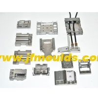
2. รูปแบบของโมดูลล็อค
โมดูลล็อคมาตรฐานมีสองรูปแบบ สำหรับโมดูลล็อครูรูปเอวที่ใช้กันทั่วไปเว้นแต่ว่าลูกค้าจะได้รับการร้องขอโมดูลล็อครูปตะขอโดยทั่วไปจะไม่ถูกนำมาใช้
3. ขนาดโมดูลล็อค
ขนาดของโมดูลล็อคขึ้นอยู่กับขนาดของแม่พิมพ์ ในหมู่พวกเขา A และ B ขึ้นอยู่กับปริมาณและความหนาของเทมเพลตที่จะล็อค E ถูกนำมาเป็น 10-15 มม. และ D เท่ากับเส้นผ่านศูนย์กลางของสกรูบวก 1 มม.

4. การประกอบโมดูลล็อค
โดยทั่วไปแล้วแม่พิมพ์จะต้องติดตั้งโมดูลล็อคสองโมดูลซึ่งตั้งอยู่ทั้งสองด้านของแม่พิมพ์และจัดเรียงสมมาตร
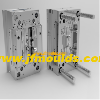
สอง: คอลัมน์สนับสนุน
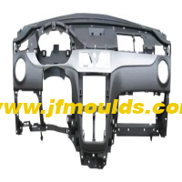
คอลัมน์สนับสนุนหรือที่รู้จักกันในชื่อคอลัมน์สนับสนุนส่วนใหญ่จะใช้เพื่อทนต่อแรงขยายที่กระทำโดยการหลอมละลายบนเทมเพลตที่เคลื่อนไหวในระหว่างกระบวนการฉีดขึ้นรูปของแม่พิมพ์ป้องกันไม่ให้เทมเพลตที่เคลื่อนไหวจากการเปลี่ยนรูปภายใต้การกระทำของแรงขยายตัวและเพิ่มความแข็งแกร่งของแม่พิมพ์ รูปร่างของคอลัมน์รองรับเป็นรูปทรงกระบอกและวัสดุเป็นเหล็ก 45 หรือเหล็กเกรดสีเหลือง S50C

1. การประกอบคอลัมน์สนับสนุน
คอลัมน์รองรับจะถูกยึดเข้ากับแผ่นฐานของแม่พิมพ์ที่เคลื่อนที่ด้วยสกรู
ข้อควรระวังการชุมนุม
1. ตำแหน่งของคอลัมน์สนับสนุนควรอยู่ใกล้ที่สุดเท่าที่จะเป็นไปได้จนถึงกลางแม่พิมพ์ หากพื้นที่อนุญาตให้มีขนาดเส้นผ่านศูนย์กลางควรมีขนาดใหญ่ที่สุดเท่าที่จะทำได้
2. Chamfer ที่ไม่ได้ทำเครื่องหมาย C = 1
3. ใช้เวลา 1.5 ถึง 2.0 มม. ที่ด้านหนึ่งของต่อมระหว่างคอลัมน์รองรับและแผ่นก้านดันนั่นคือ D = D (3 ถึง 4 มม.)
4. คอลัมน์สนับสนุนจะต้องสูงเท่ากับเหล็ก ความสัมพันธ์มีดังนี้:
เมื่อมิติความกว้างของแม่พิมพ์น้อยกว่า 300 มม.: H1 0.05 มม.;
เมื่อความกว้างของแม่พิมพ์น้อยกว่า 400 มม.: H1 0.1 มม.;
เมื่อความกว้างของแม่พิมพ์อยู่ระหว่าง 400 ถึง 700 มม.: H1 0.15 มม.;
When the width of the mold is greater than 700mm :H1=H 0.2mm
The distance between the support columns and the square irons should be no less than 25mm.
The distance between the support columns should not be less than 35mm and should not exceed 80mm

(2) Specifications and dimensions of the support columns
The specification and model representation of the support column is :SP- Diameter length.

1. Determination of the number of guard posts
If the support column is too large, it will mostly affect the rigidity and size of the push rod plate. If there are too few forks, it is difficult to ensure the rigidity of the mold. The rationality and quantity of the support columns can be determined by calculating the total area that the mold needs to support. The total area that needs to be supported can be referred to the following calculation method.
Calculate the area A between two pieces of iron: if the length of the push rod plate is 1 and the distance between the pieces of iron is W, then A- Lw.
2. The coefficient n1 is determined based on the area A between the square irons, as shown in Table 3-12.
3. Determine a certain coefficient n2 based on the distance W between the square irons.
4. Calculate the total area of the supports (I .e., the sum of the areas of the support columns) : S= an - 1-2.
The above are the calculated quantities. However, in the actual design process, due to the priority consideration of the positions and quantities of the push rods, diagonal push rods, guide columns of the push rod plate and K.O holes (the support columns must not interfere with these structures), the size and quantity of the support columns are often restricted. If the total area of the support columns is far from the calculated area, the solution is to increase the thickness of the moving die B plate by 10mm or 20mm.
Car Mould_Taizhou jiefeng Mold Co.,Ltd. (jfmoulds.com)

ข้อมูลที่เกี่ยวข้อง
โซลูชั่นสำหรับสายอากาศ, charring, ลวดติดขัด, ความสูงระดับความสูงหรืออากาศที่ติดอยู่ในแม่พิมพ์
2025-08-14
โซลูชั่นสำหรับสายอากาศ, charring, ลวดติดขัด, ความสูงระดับความสูงหรือติดอยู่ ...
การวิเคราะห์เชิงลึกของแม่พิมพ์ฉีด: การสำรวจแบบเต็มกระบวนการตั้งแต่การออกแบบไปจนถึงการใช้งาน
2025-07-10
การวิเคราะห์เชิงลึกของแม่พิมพ์ฉีด: การสำรวจแบบเต็มกระบวนการตั้งแต่การออกแบบไปจนถึง...
วิวัฒนาการที่ประสานกันของการไตร่ตรองทางเทคโนโลยีและระบบนิเวศอุตสาหกรรม
2025-07-15
วิวัฒนาการที่ประสานกันของการไตร่ตรองทางเทคโนโลยีและระบบนิเวศอุตสาหกรรม Mi...
การปรับระดับความสูงของแม่พิมพ์สีขาวและพื้นผิวจะได้รับการแก้ไขได้อย่างไร
2025-08-26
การยกระดับพื้นผิวสีขาวและพื้นผิวของแม่พิมพ์สามารถแก้ไขได้อย่างไรสีขาวด้านบน o ...
โซลูชันสำหรับเครื่องหมายอากาศที่ตำแหน่งลูกศรในทิศทางของแม่พิมพ์เส้นเงาสีดำ (เส้นฟิวชั่น) บนพื้นผิวและจุดที่ติดอยู่กับดักและจุดสีขาวที่ตำแหน่งรูโคมไฟ
2025-08-13
โซลูชั่นสำหรับเครื่องหมายอากาศที่ตำแหน่งลูกศรในทิศทางแม่พิมพ์ ...

ความขรุขระพื้นผิวของชิ้นส่วนพลาสติกและการเลือกเครื่องฉีดขึ้นรูป
2025-09-18
ความขรุขระพื้นผิวของชิ้นส่วนพลาสติกและการเลือกเครื่องฉีดขึ้นรูป 1 ....